
For electronic R&D engineers, an oscilloscope serves as the primary window into circuit behavior. We rely on this instrument to inspect transient electrical signals and validate design performance. However, this “window” can sometimes present a distorted view. In many cases, the displayed waveform does not reflect actual operating conditions. To minimize oscilloscope waveform measurement errors, engineers must master underlying principles rather than relying solely on automated functions. Understanding these mechanisms ensures you capture authentic signal representations consistently.
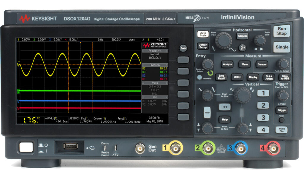
Auto-Set Limitations Causing Oscilloscope Waveform Measurement Errors
Nearly all modern oscilloscopes feature an “Auto-Set” button. This function automatically adjusts vertical sensitivity (V/div) and horizontal timebase based on input signals. While convenient for initial visualization, Auto-Set displays waveforms quickly but rarely provides optimal measurement settings. Manual optimization remains essential for accurate data acquisition and avoiding oscilloscope waveform measurement errors.
To maximize ADC vertical dynamic range, adjust scales so waveforms occupy 70%–80% of screen height. More critically, verify trigger configurations. Auto-Set typically selects channels with largest amplitudes as trigger sources, which may not align with diagnostic needs.
Consider measuring timing between an intermittent Channel 2 pulse and Channel 1 clock. After Auto-Set, the scope triggers on stable Channel 1. Consequently, Channel 2 appears unstable because acquisition begins at Channel 1 edges. Only manual trigger source switching stabilizes the display for precise analysis. Therefore, treat Auto-Set as a starting point for signal integrity measurement, never a final solution.
Business Value Highlight: Correct trigger configuration prevents timing violation misdiagnosis. This reduces debugging cycles and accelerates validation timelines, directly improving time-to-market metrics for competitive advantage.
Probe Issues Behind Common Oscilloscope Waveform Measurement Errors
The probe bridges the Device Under Test (DUT) and oscilloscope. Despite simplicity, improper probing frequently causes oscilloscope waveform measurement errors. These artifacts often mimic circuit faults, leading engineers down wrong diagnostic paths.
Ground Lead Inductance Effects
Standard passive probes include signal tips and ground leads. Any conductor possesses inherent inductance. Long alligator clip ground leads create parasitic inductance (L) that forms LCR resonant circuits with probe capacitance (C). During fast transitions, this resonance excites “ringing” oscillations. Engineers might waste time adjusting driver strength when root causes are simply excessive ground inductance.
Replace long ground leads with ground springs or short copper loops near probe tips. Additionally, long grounds form loop antennas coupling external noise. Maintaining shortest possible ground paths is mandatory even for low-frequency measurements.
Executing Proper Oscilloscope Probe Compensation
Some engineers connect circuits directly via coaxial cables. While acceptable in 50Ω RF environments, this practice damages high-impedance circuits. Oscilloscope inputs have 10pF+ capacitance; coaxial cables add ~100pF/m. This capacitive load alters rise times and compromises bandwidth significantly.
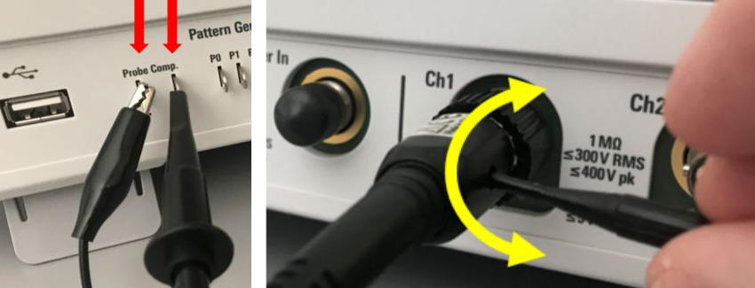
Standard 10:1 passive probes maintain low input capacitance (<10pF). To ensure flat frequency response, oscilloscope probe compensation is mandatory. Connect probes to calibration outputs and adjust trimmers until square waves show flat edges. Neglecting this causes amplitude errors during high-frequency pulse measurements. Always recheck after changing probes or channels.
Business Value Highlight: Proper probing eliminates false test failures. This prevents costly redesigns from chasing artifacts and ensures first-pass yield accuracy during manufacturing validation phases.
Sampling Rate Aliasing in Oscilloscope Waveform Measurement Errors
Digital oscilloscopes reconstruct waveforms through sampling. Nyquist theorem requires sampling rates exceeding twice the highest frequency. Practically, capturing fast edges needs 3–5 samples per transition. Insufficient sampling creates sampling rate aliasing, a major source of oscilloscope waveform measurement errors.
Sampling rates adjust based on timebase and record length. When observing long-duration signals, slower timebases force reduced sampling to fit finite memory. Wide sampling intervals miss rapid changes entirely.
A critical misconception involves zooming into low-rate captures. If original acquisition lacked samples, scaling reveals only interpolation, not true details. Always verify actual sampling rates support required bandwidth before analyzing fine features.
Digital Storage Oscilloscope Solutions for Intermittent Errors
Engineers sometimes assume analog scopes better reveal variations. While analog excels in real-time display, it struggles with rare events. Low-frequency intermittent signals may not excite CRT phosphors visibly.
Modern digital storage oscilloscope technology offers distinct advantages. Once captured, events display clearly regardless of frequency. Advanced features visualize phenomena invisible to analog systems, reducing oscilloscope waveform measurement errors from missed transients.
Extended persistence modes accumulate intermittent glitches. Advanced triggers like pulse width precisely isolate specific anomalies. These tools resolve complex signal integrity measurement issues traditional methods miss.
Mastering oscilloscope operation combines art and science. Every decision influences fidelity. By understanding technical foundations, engineers avoid common oscilloscope waveform measurement errors and ensure observations reflect true behavior. For PCB assembly requiring precise validation, contact our engineering team today. We also offer PCB fabrication capabilities aligned with IPC-A-610 Class 3 standards.
FAQ: Resolving Oscilloscope Waveform Measurement Errors
Q1: Why does my oscilloscope show ringing despite correct circuit design?
A: Excessive ground lead inductance forms LCR resonance with probe capacitance. Replace alligator clips with ground springs. Verify oscilloscope probe compensation afterward to ensure flat response and eliminate oscilloscope waveform measurement errors.
A: Excessive ground lead inductance forms LCR resonance with probe capacitance. Replace alligator clips with ground springs. Verify oscilloscope probe compensation afterward to ensure flat response and eliminate oscilloscope waveform measurement errors.
Q2: Can I trust zoomed details from long-capture recordings?
A: Not if original sampling was low. Zooming reveals interpolation, not true signals. Check real-time sampling indicators before trusting details. Ensure adequate samples exist across transitions during initial capture to prevent aliasing-related oscilloscope waveform measurement errors.
A: Not if original sampling was low. Zooming reveals interpolation, not true signals. Check real-time sampling indicators before trusting details. Ensure adequate samples exist across transitions during initial capture to prevent aliasing-related oscilloscope waveform measurement errors.
Q3: How do I capture disappearing intermittent glitches reliably?
A: Use advanced triggers (pulse width, runt) on modern digital storage oscilloscope platforms. Combine with infinite persistence to accumulate rare events. Digital instruments retain data permanently once triggered, unlike analog scopes that lose infrequent signals.
A: Use advanced triggers (pulse width, runt) on modern digital storage oscilloscope platforms. Combine with infinite persistence to accumulate rare events. Digital instruments retain data permanently once triggered, unlike analog scopes that lose infrequent signals.
Q4: Is Auto-Set sufficient for multi-channel timing validation?
A: No. Auto-Set optimizes display stability, not accuracy. It often selects wrong trigger sources. Manually configure trigger parameters matching your test requirements. Adjust vertical scales to 70%–80% ADC range for optimal resolution and minimal oscilloscope waveform measurement errors.
A: No. Auto-Set optimizes display stability, not accuracy. It often selects wrong trigger sources. Manually configure trigger parameters matching your test requirements. Adjust vertical scales to 70%–80% ADC range for optimal resolution and minimal oscilloscope waveform measurement errors.
 日本語
日本語  English
  Русский
  Français
  Deutsch
  한국어
한국어  Español
  Português
  العربية
  Türkçe
  Italiano
  Polski
  Dansk
Dansk