
A temperature sensor reads 25.3 °C on your prototype but drifts to 26.1 °C after two hours of runtime. The MCU datasheet promises a 12-bit ADC, yet your measurements look noisy and inconsistent. This scenario frustrates many engineers during validation. Before blaming the sensor or rewriting firmware, you must verify whether the MCU built-in ADC vs dedicated ADC choice actually matches your signal chain requirements.
Most physical signals in industrial and consumer electronics are analog. Temperature, pressure, audio, current, and displacement all vary continuously. Your digital processor needs an A-D converter to translate these real-world voltages into discrete codes. System designers generally face two paths: integrate the conversion inside the microcontroller or add a specialized ADC IC. Understanding this trade-off prevents costly respins later.
ADC Fundamentals: Sampling Rate and Resolution
Evaluating any converter starts with two basic specs. Sampling rate, measured in samples per second (sps), defines the maximum signal frequency you can capture without aliasing. According to the Nyquist theorem, you need at least twice the signal bandwidth. In practice, however, we usually target 2.5× or higher to leave headroom for anti-aliasing filters and phase margin.
Resolution indicates how many discrete levels the ADC can distinguish across its input range. An N-bit converter theoretically provides 2^N codes. For instance, an 8-bit ADC yields 256 steps, while a 12-bit unit offers 4,096 steps. Higher resolution means finer voltage granularity.
Nevertheless, high resolution does not guarantee high accuracy. Resolution only describes code width. True accuracy depends on integral nonlinearity (INL), differential nonlinearity (DNL), offset error, gain error, noise floor, reference stability, and even mixed-signal PCB layout. Always check these parameters instead of trusting bit count alone.
Common ADC Architectures Explained
Different applications demand different converter topologies. Here is how four mainstream architectures compare in actual engineering builds:
In the low-speed, high-precision domain below 10 Msps, SAR and ΔΣ dominate. SAR converters excel in general-purpose tasks with modest power budgets. Delta-Sigma units leverage oversampling and digital filtering to push effective resolution toward 24 or even 32 bits, though reducing their power consumption remains challenging.
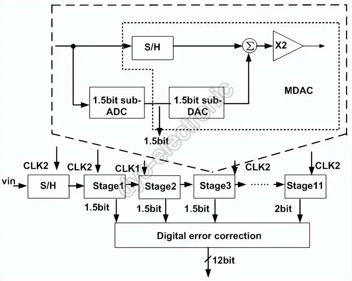
For high-speed work, Flash ADCs use massive parallel comparators to achieve multi-Gsps rates, sometimes using time-interleaving techniques exceeding 40 Gsps in oscilloscopes. Pipeline ADCs sacrifice some speed for better resolution at moderate frequencies. Critically, evaluating difficulty requires considering “resolution × frequency” together. An 8-bit, 1 GHz channel is as demanding as a 14-bit, 100 MHz system because both stress analog front-ends, clock distribution, and power integrity equally hard.
Engineer’s Note: Future trends favor lower power across all architectures. Modern portable instruments cannot tolerate the thermal dissipation of older high-performance designs. Lower supply voltages help, but they also shrink noise margins, making board-level cleanliness more important than ever.
Why Resolution Is Not Accuracy
This distinction causes more field failures than almost any other spec misunderstanding. Resolution tells you how fine the ruler’s markings are. Accuracy tells you whether those markings are correctly placed.
Consider a 0–10 V input range. With 10 display levels, each step represents ~1 V. With 4,096 levels, each step is ~2.44 mV. Finer steps improve readability but do not fix a bent ruler. An audio ADC might offer 24-bit resolution yet perform poorly at DC because it intentionally blocks low frequencies. Using such a part for precision DC measurement would be a mistake.
Actual accuracy errors include offset voltage, parasitic capacitance, residual impedance, reference drift, gain error, temperature coefficients, and nonlinearity. Therefore, always remember: resolution ≠ accuracy. Confirm INL, DNL, offset, full-scale error, noise, and reference conditions whenever precision matters.
Understanding INL and DNL Specifications
Nonlinearity describes how far the real transfer function deviates from an ideal straight line. Specialized ADCs split this into two metrics:
- Integral Nonlinearity (INL): Measures overall curve deviation from the best-fit or endpoint line. Large INL means the output code misrepresents the true input regardless of calibration. Simple offset/gain trimming cannot fix it.
- Differential Nonlinearity (DNL): Measures the width error between adjacent codes relative to 1 LSB. Severe DNL causes missing codes where certain digital values never appear. Worse still, non-monotonic behavior can turn negative feedback loops into positive ones, destabilizing motor controllers or power regulators.
In closed-loop systems, monotonicity often matters more than absolute accuracy. Always verify DNL guarantees when designing servo, regulation, or safety-critical feedback paths.
Real Performance of On-Chip ADC Performance
Historically, A-D converters were standalone ICs. Mixed-signal process advances eventually allowed integration directly onto microcontrollers. This approach saves board space, reduces BOM cost, and simplifies assembly. However, placing sensitive analog circuits next to noisy digital logic creates inherent compromises.
Most on-chip ADC performance targets 8–12 bit nominal resolution. For consumer gadgets, button sensing, battery monitoring, or rough temperature tracking, this suffices. Cost advantages shine in high-volume production. Yet effective precision typically falls 1–2 bits below the datasheet headline number.
Why? Boosting analog performance increases die area, isolation complexity, test time, and fabrication cost. These factors erode the primary value proposition of integrated MCUs. Manufacturers therefore optimize for “good enough” rather than laboratory-grade specs. If your application truly needs stable 10-bit results, treat a “12-bit” MCU ADC as potentially marginal.
Can You Achieve 0.1% Measurement Accuracy?
Suppose your design requires 0.1% total error. Quantization error alone sets a hard floor:
An 8-bit converter cannot meet 0.1% because quantization already exceeds the budget. A 10-bit part leaves only ±0.05% for all other error sources combined. That demands sub-0.5 LSB performance from nonlinearity, offset, gain, reference, and analog front-end simultaneously. Most standard MCU ADCs cannot deliver this consistently.
Take the ADC108S022, a dedicated 10-bit SAR device rated 50–200 ksps. Its INL reaches ±0.3 LSB max, offset ±0.7 LSB max, and full-scale error ±0.4 LSB max. After calibration, remaining errors might approach 0.1%, but design margin stays razor-thin. External resistors, references, and layout must be near-perfect.
Consequently, 12-bit ADC for precision measurement is the pragmatic starting point for 0.1% targets. The smaller quantization error (±0.0125%) grants ample headroom for real-world imperfections. The slightly higher component cost pays for itself through relaxed analog design and improved yield.
Advantages and Limits of Integrated Converters
The biggest win for integrated solutions is simplicity. No extra chip, no SPI/I²C routing, no separate power sequencing. Just connect the signal, configure registers, and sample. Benefits include lower BOM cost, reduced PCB footprint, tighter software control, and seamless DMA/timer integration. Battery voltage checks, potentiometer reading, simple current sensing, and keypad scanning rarely justify external parts.
However, limitations are real. Digital switching noise couples through substrate and bond wires. Internal references track supply rail ripple. Input sampling capacitors require adequate charging time within the acquisition window. High source impedance or excessive RC filtering introduces settling errors. Multiplexer crosstalk worsens when adjacent channels have large voltage differences. Ground bounce from I/O toggling corrupts sensitive conversions.
Actually, effective resolution often drops below nominal specs. A “12-bit” MCU ADC may only deliver 10 usable bits in a noisy environment. Reference quality directly modulates output codes since conversion is fundamentally a ratio measurement. Using VDD as VREF ties measurement stability to regulator PSRR and load transient response.
Procurement Tip: When planning electronic component sourcing, verify ADC availability early. Dedicated precision ADCs sometimes have longer lead times than commodity MCUs. Locking in supply agreements during design phase avoids production delays later.
Decision Framework: When to Use External ADC Over MCU
Selection hinges on system requirements, not marketing claims. Apply this practical checklist during architecture reviews:
- Stick with MCU built-in ADC when: Signals change slowly, amplitudes are large, and 1–2% accuracy suffices. Examples include battery gauging, thermal trend monitoring, user interface inputs, and cost-sensitive consumer products. Add software averaging, proper RC filtering, and clean reference selection to maximize usable performance.
- Choose dedicated ADC when: You need 0.1%+ accuracy, guaranteed linearity, low noise floor, high SNR, synchronous multi-channel sampling, differential inputs, or defined AC performance. Industrial metrology, medical instrumentation, precision current shunts, and audio signal chains typically fall here.
General rules of thumb from years of debugging:
- 8-bit works for ~1% rough estimates.
- 10-bit handles general sensing but struggles at 0.1%.
- 12-bit is the safe baseline for 0.1% precision.
- 16+ bits serve lab-grade instruments and low-frequency transducers.
- ΔΣ fits slow, high-resolution tasks.
- SAR covers general-purpose, multi-channel, low-power needs.
- Pipeline balances medium-high speed with decent resolution.
- Flash enables extreme speed at modest bit counts.
Ultimately, system performance emerges from the entire signal chain: architecture, sample rate, resolution, INL/DNL, noise, reference, analog front-end, filtering, power delivery, mixed-signal PCB layout, calibration, and firmware processing. Stop asking “how many bits?” Start asking “can this converter reliably deliver trustworthy data within my bandwidth, error budget, power, cost, and size constraints?”
If your current design sits on the fence, share your signal specs and error budget with us. We regularly review MCU built-in ADC vs dedicated ADC trade-offs during DFM consultations and can flag potential issues before tape-out.
Frequently Asked Questions
What is the main difference between MCU built-in ADC vs dedicated ADC in terms of accuracy?
Dedicated ADC chips typically offer superior INL, DNL, and noise performance because they isolate analog circuits from digital switching noise. While an MCU built-in ADC vs dedicated ADC comparison shows integrated units save cost and space, their effective accuracy often falls 1–2 bits below nominal specs due to substrate coupling and shared references.
When should I choose an external ADC chip instead of using the MCU’s internal converter?
Select an external ADC chip when your application demands 0.1%+ accuracy, guaranteed monotonicity, low noise, synchronous sampling, or differential inputs. If your signal chain requires precision beyond what on-chip ADC performance can reliably provide despite careful layout and calibration, the added component cost prevents costly field failures and rework.
How do INL and DNL affect ADC selection for precision measurement?
INL determines overall transfer curve deviation that calibration cannot fix, while DNL affects adjacent code width and monotonicity. For 12-bit ADC for precision measurement targeting 0.1% accuracy, both parameters must stay well below 1 LSB. Always verify these specs alongside resolution, since high bit count alone does not guarantee usable accuracy in closed-loop or metrology applications.
 English
  Русский
  Français
  Deutsch
  日本語
日本語  한국어
한국어  Español
  Português
  العربية
  Türkçe
  Italiano
  Polski
  Dansk
Dansk