
A missing aperture definition in your PCB Gerber files can halt a production line for days. We have seen entire batches of bare boards scrapped because the solder mask layer did not align with the copper pads, all due to a corrupted vector coordinate in the output zip. These files are not just digital paperwork; they are the direct machine instructions that translate your CAD design into physical hardware.
Understanding what these files actually contain prevents expensive re-spins. Below, we break down the formats, generation process, and documentation standards that keep manufacturing running smoothly.
What Are PCB Gerber Files Exactly?
Originally developed by Gerber Scientific (founded by Joseph Gerber), this format became the universal benchmark for consistent printed circuit board production. A PCB Gerber file details every requirement across each stage of product development, serving both PCB fabrication and assembly workflows.
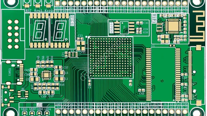
Technically, these are open ASCII vector format files. They encode information for every single layer of the board. Vias, solder mask openings, silkscreen text, and copper traces all exist as precise vector coordinates rather than pixels. Manufacturing equipment reads these coordinates directly to expose film or drive laser plotters.
Common File Extensions
Most modern CAD tools generate these outputs in the RS-274X format. You will typically encounter two extensions:
.gb.gbr
Both carry identical ASCII vector data. The choice between them usually depends on the specific EDA tool’s default naming convention rather than any functional difference.
How PCB Gerber Files Are Generated
Generating accurate output requires more than clicking “export.” After completing your layout, you must produce an individual file for each board layer. Additionally, separate files are needed for the solder mask, top/bottom silkscreen, and top/bottom solder paste layers. Some contract manufacturers also request specific assembly layers if your design has unique configurations.
Actually, the most critical step happens before export: configuring the generator settings. Ensuring consistent units (millimeters vs. inches) and decimal places avoids scaling disasters later. We always recommend zipping all layers into a single archive with descriptive filenames so the CAM engineer instantly knows which file corresponds to which layer.
Engineer’s Note: Always include a stackup drawing labeled alongside your PCB Gerber files inside the zip. This visual map eliminates guesswork about layer order and prevents misalignment during lamination.
Don’t Forget the NC Drill File
These vector files define planar features, but holes require separate instructions. The NC Drill file tells the drilling machine exactly where to place vias and mounting holes. Without it, your perfectly defined copper layers have no way to connect vertically. Treat this file as equally mandatory.
Four Key PCB Gerber Formats Explained
Not all formats offer the same level of reliability. Here is how the four main standards compare in actual production environments.
RS-274-D (Legacy)
This numerical control format dates back to 1970s photo plotters. It requires manual input of D-codes (aperture definitions) via a separate wheel file. Because of this separation, mismatched aperture lists cause frequent plotting errors. Consequently, its use is now heavily restricted, and most modern CAM systems flag it as deprecated.
RS-274X (Current Industry Standard)
In use since 1998, this embedded format solved the legacy problems by including units, format, and aperture data within the file itself. Key advantages include:
- Support for polygon fill commands and polarity controls
- Elimination of manual D-code entry
- Reduced photo plotting errors through self-contained metadata
- Compatibility with virtually all current CAM software
For most standard orders, RS-274X remains the safest bet.
ODB++ (Intelligent Data Model)
This highly standardized input format automates stackup, drill placement, and netlist labeling. Most major CAD programs support it natively. The real benefit here is error reduction: because naming conventions and layer mapping are automated, there is almost no room for manual misinterpretation. However, some older fabrication shops may still prefer traditional Gerber outputs.
Gerber X2 (Modern Advanced Format)
As the latest evolution supported by advanced CAM applications, X2 adds semantic attributes directly into the file. It explicitly defines:
- The function of each file (e.g., “top solder mask”)
- The component represented by pad geometries
- Pad functions (via, test point, fiducial)
That said, adoption is still growing. Always verify your manufacturer supports X2 before switching from RS-274X.
Essential Documentation Beyond PCB Gerber Files
Submitting vector data alone invites risk. Robust manufacturing documentation ensures your intent survives the handoff. At minimum, include these five items:
- Fabrication & Assembly Drawings: Visual references for dimensions, tolerances, and special requirements.
- Pick & Place Data: Centroid files for automated SMT component placement.
- Test Data: Netlist or flying probe specifications for electrical verification.
- Schematic Netlist: Cross-reference for CAM engineers to validate connectivity against the layout.
- Readme File: Plain-text notes highlighting revisions, known issues, or special handling instructions.
Working closely with your contract manufacturer catches gaps early. For instance, our PCB assembly team reviews incoming packages against this exact checklist before loading any job onto the line.
ISO 9001certification ensures our file review process meets international quality management standards. When you submit complete documentation, turnaround times drop significantly because engineering queries decrease.
Frequently Asked Questions About PCB Gerber Files
Can I send native CAD files instead of PCB Gerber files?
Some manufacturers accept native formats like Altium or KiCad projects, but this introduces version compatibility risks. PCB Gerber files remain the universal language because they are vendor-neutral. Generating them yourself gives you full control over what gets manufactured, eliminating interpretation errors from outdated CAD viewers.
What is the difference between RS-274X and Gerber X2?
RS-274X contains geometric data only, requiring CAM engineers to infer layer function from filenames. Gerber X2 embeds semantic metadata (file function, pad purpose) directly in the code. While X2 reduces ambiguity, RS-274X is still widely accepted and sufficient for most standard designs when paired with proper documentation.
Why does my PCB Gerber file look wrong in the viewer?
Common causes include incorrect decimal precision settings, mixed unit systems (mm/inch), or missing aperture definitions. Always configure your generator consistently before export. If vectors appear disconnected or oversized, check that your viewer matches the format specification used during generation.
Do PCB Gerber files include drill data?
No. Vector files define planar features only. You must generate a separate NC Drill file for all holes, vias, and slots. Submitting PCB Gerber files without accompanying drill data will result in incomplete boards. Bundle both in the same zip archive with clear labeling.
Ready to validate your next design package? Send us your PCB Gerber files for a free DFM review. Our engineering team checks format compliance, layer alignment, and drill registration before quoting—catching errors that cost thousands in rework. Request your competitive quote today atTalk to us before you route:
- Contact: Spancer Huang
- WhatsApp: +86 15818610980
- Email: info@dyc-electronic.com
 Português
  English
  Русский
  Français
  Deutsch
  日本語
日本語  한국어
한국어  Español
  العربية
  Türkçe
  Italiano
  Polski
  Dansk
Dansk