NMOS and PMOS Transistors: Fundamentals and Applications
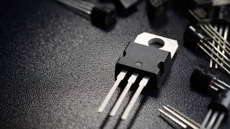
In this article, we will delve into the structure and operation of NMOS and PMOS transistors, and discuss the applications and characteristics of these essential components in electronic circuits. Introduction MOS (Metal-Oxide-Semiconductor)- NMOS (N-Channel MOS) and PMOS (P-Channel MOS) transistors play a crucial role in modern electronics. These transistors provide the basic building blocks for a wide range of devices, from microprocessors to memory chips. The most significant use of MOSFET transistors is in VLSI design due to their small size. A trillion MOSFETs are fabricated on a single chip. The development has led to significant advancements in technology and enabled the miniaturization of even more electronic components. 1. MOS […]
Linear vs Switching Power Supply: Understanding the Differences
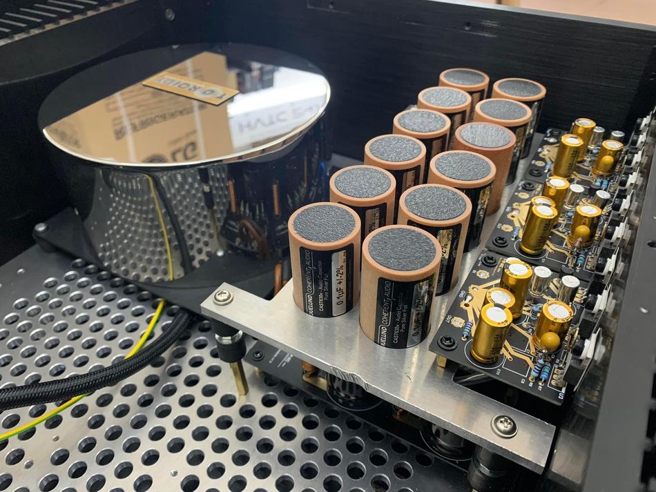
This article delves into the core concepts of linear vs switching power supply, exploring their efficiency, noise levels, and other key factors, that help make the right choice for your projects! Precise Variable Voltage (V) and Current (I) Power Supply used in Prototyping Introduction Power supplies, or PSUs, are essential components in electronic devices, converting raw AC power into usable DC voltage. The debate between two primary types: linear vs switching power supply has long been a central topic for engineers and designers aiming to optimize their systems. While linear power supplies offer simplicity and low-noise output, switching power supplies excel in efficiency and compactness. Understanding the differences between linear vs […]
FPGA vs Microcontroller Understanding the Key Differences and Use Cases
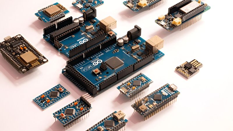
FPGAs are reconfigurable hardware used for parallel, high-speed processing, while microcontrollers are fixed-architecture chips designed for sequential, control-oriented tasks. FPGAs offer flexibility and performance MCUs provide low power, ease of use, and cost-efficiency. Introduction Field-Programmable Gate Arrays (FPGAs) and microcontrollers (MCUs) are two foundational components in embedded systems and digital electronics. Both serve as tiny computation engines embedded within devices –but they differ sharply in how they operate, how they are programmed and where they’re most effective. . FPGAs are reconfigurable hardware platforms that allow custom digital circuits to be configured after manufacturing, whereas microcontrollers are fixed-architecture processors designed to execute software instructions. These differences in architecture lead to distinct capabilities, performance characteristics, and […]
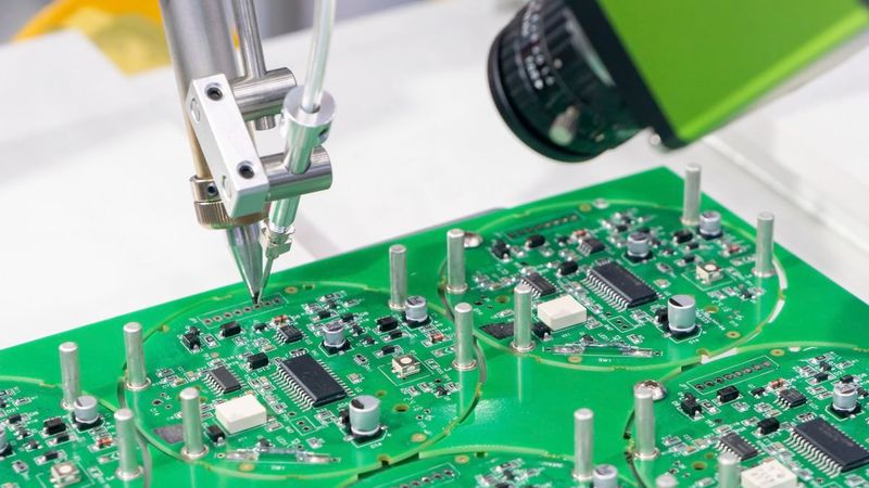
What is SMT: A Comprehensive Guide to Surface Mount Technology
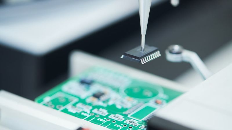
Surface Mount Technology (SMT) revolutionized electronics manufacturing by enabling smaller, faster, and more efficient circuit designs. This guide delves into the core principles of SMT, explores its cutting-edge advancements, and addresses the challenges in implementing this technology. Introduction Surface Mount Technology (SMT) is a pivotal innovation in modern electronics, enabling the development of smaller, faster, and more efficient devices. SMT has streamlined manufacturing processes by allowing components to be mounted directly onto the surface of printed circuit boards (PCBs) and opened the door to advanced designs. It has contributed to miniaturized electronics, paving the way for portable devices after making them more space-efficient and compact. As a result, SMT is […]
Types of Solder: A Comprehensive Guide for Engineering Professionals
Explore the different types of solder, their unique properties, and their critical roles in various engineering applications. Understand how to choose the right solder for your project and the considerations involved. Introduction Solder forms the critical connections in electronic devices, ensuring their functionality and reliability. All types of solder act as connective tissues that glue the electronic components to the PCB substrate, ensuring connectivity to the circuit board. Its low melting point makes it one of the most intriguing elements of PCB design and without a solder, it would be hard to imagine the state of modern electronics. While solder is a low melting-point metallic alloy, several types of solder […]
Tented Vias in PCB Design: A Comprehensive Guide to Theory and Best Practices
Discover what tented vias are in PCB design and how to use them effectively – covering their definition, benefits, drawbacks, and best practices from design through manufacturing! Introduction Tented vias are an essential aspect of modern PCB design, offering a reliable solution for enhancing circuit board performance and reliability. These vias are covered with solder mask to prevent contamination, reduce the risk of short circuits, and improve electrical insulation. By eliminating unnecessary exposure to environmental factors, tented vias contribute to enhanced signal integrity and durability, making them a preferred choice in high-density and high-frequency PCB layouts. Designers implement tented vias to optimize space utilization and protect underlying copper traces, particularly in […]
Cleaning Circuit Boards: A Complete Guide for Engineers and Technical Professionals
Learn the best methods and industry standards for cleaning circuit boards, removing contaminants like dust, flux residues, and corrosion to ensure optimal performance and longevity! Introduction Cleaning circuit boards is an essential maintenance task in electronics engineering! Even the best-designed printed circuit boards (PCBs) can suffer performance issues or failures if contaminants build up on their surfaces. Dust, flux residue from soldering, and corrosion deposits can all disrupt the delicate electrical pathways on a PCB. For example, a layer of dust can block airflow and insulate heat, causing components to overheat. Dirt combined with humidity can accelerate corrosion on component leads and PCB traces. Flux residues left after soldering are hygroscopic – they absorb moisture – and can […]
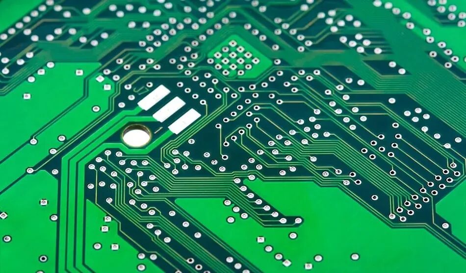
Vcc vs Vdd: Differences, Usage, and Best Practices in Modern Electronics
This article is a detailed guide on Vcc vs Vdd power rail naming conventions in analog and digital circuits (CMOS vs bipolar), with practical tips for schematics, PCB layout, and IC selection! Printed Circuit Board (PCB) Introduction In modern electronics, understanding power supply terminology is critical for accurate circuit design and analysis. The most frequently encountered terms are Vcc and Vdd, both of which refer to voltage supply rails but differ significantly in context and application. The distinction between Vcc vs Vdd reflects the underlying transistor technology (BJT vs. MOSFET) and impacts everything from schematic labeling to voltage regulation strategies. Ultimately, a clear understanding of Vcc vs Vdd contributes to more robust and reliable electronic designs. In this article, we’ll explore the technical differences […]