
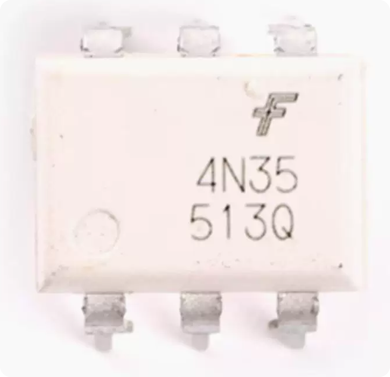
The 4N35 optocoupler remains a cornerstone in electronic manufacturing even in 2025. Despite newer digital isolators entering the market, this classic 6-pin DIP part anchors isolation circuits in industrial controls, power supplies, and motor drives. For procurement teams and design engineers alike, understanding its internal structure, operating modes, and critical specifications ensures reliable production outcomes. This guide covers everything from fundamental working principles to practical PCBA sourcing strategies.
What Is the 4N35 Optocoupler and How Does It Work?
The 4N35 optocoupler is a galvanic isolation component that transmits electrical signals between two isolated circuits using light as the medium. Specifically, an infrared LED (Light Emitting Diode) faces a silicon phototransistor across a dielectric barrier inside the package. When the LED activates, it emits infrared light that triggers the phototransistor, passing signals without any direct electrical connection.
This optical isolator blocks high voltages while maintaining signal integrity. According to Vishay’s technical datasheet, the device withstands 5,000 V RMS isolation voltage. Therefore, designers trust this component to separate low-voltage logic from noisy mains domains safely.
Internal Structure Breakdown
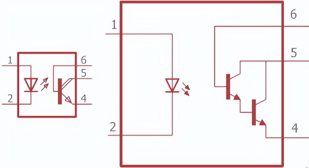
The internal structure of the 4N35 optocoupler consists of three functional zones:
- Light Emission Zone (Pins 1–2): An infrared LED driven by the input circuit. When forward current flows, the LED emits light at a specific wavelength.
- Dielectric Isolation Gap: The space between the LED and phototransistor is filled with transparent non-conductive material—typically glass, air, or transparent plastic. This gap provides electrical isolation typically rated at 5 kV RMS or higher.
- Light Reception Zone (Pins 4–6): A silicon NPN phototransistor whose base region is activated by incoming infrared photons. The collector and emitter switch the output circuit, functioning identically to a standard BJT (Bipolar Junction Transistor).
Additionally, Pin 6 provides external access to the phototransistor base. This feature enables sensitivity adjustment and is critical for field calibration in precision applications.
Business Value Highlight: Understanding the internal structure helps procurement teams evaluate counterfeit risks. Fake units often use inferior dielectric materials that fail under high-voltage stress testing. Always request isolation voltage test reports from your PCBA fabrication partner.
Operating Modes of the 4N35 Optocoupler
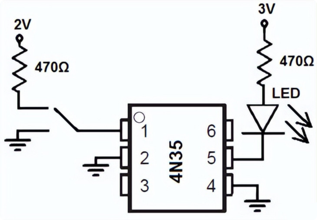
The 4N35 optocoupler operates in two distinct modes depending on the application requirements. Selecting the correct mode directly impacts circuit reliability and component lifespan.
Saturation Mode
In saturation mode, the LED switches fully ON or fully OFF. Consequently, the output phototransistor operates in either complete conduction or complete cutoff—no intermediate states exist.
This mode is ideal for applications requiring protection of microcontroller pins from high-voltage output circuits. For instance, in motor drive systems using microcontrollers, the motor demands high current and high voltage. The 4N35 optocoupler in saturation mode ensures the motor is either completely ON or completely OFF, providing clean digital isolation.
Linear Mode
In linear mode, the LED receives a varying signal pulse. The infrared light intensity changes proportionally with the input voltage or signal sample. The phototransistor then provides variable conduction at the output, faithfully reproducing analog information across the isolation barrier.
This mode is widely used in Switch-Mode Power Supplies (SMPS) for feedback loop isolation and error detection circuits. However, speed remains the primary limitation. The typical rise/fall time of 2 µs to 5 µs suits control signaling but fails at high-speed data transmission. Always confirm bandwidth requirements before selecting the 4N35 optocoupler for linear applications.
Photodiode vs. Phototransistor Comparison
For engineers evaluating alternatives, understanding the tradeoff between photodiode-based and phototransistor-based optical isolators is essential:
| Parameter | Photodiode Optocoupler | Phototransistor Optocoupler (4N35) |
|---|---|---|
| Linearity | Excellent (input light vs. output current) | Good for audio/digital, some distortion at high frequency |
| Output Amplitude | Lower | Higher (transistor gain) |
| Speed | Faster | 2–5 µs typical |
| Best For | Precision analog, high-speed | General isolation, SMPS feedback |
The phototransistor coupler can transmit wide-frequency analog audio signals by varying the LED beam entering the base region. When the beam reaches the base, the transistor output changes proportionally for amplification. However, some distortion may occur at high frequencies.
Optocoupler Type Classification: Where 4N35 Fits
Understanding the broader optocoupler landscape helps engineers select the right galvanic isolation component for each application. The 4N35 optocoupler belongs to the phototransistor category, but other types serve different purposes.
1. Phototransistor Optocouplers (DC Circuit Isolation)
Transistor-based optical isolators are used for DC circuit-related isolation. The transistor type can be PNP or NPN. Based on output pin availability, phototransistor optocouplers divide into two subtypes:
- Standard type: Collector and emitter only
- Base-access type: An additional pin (Pin 6) connects internally to the transistor base for sensitivity control
Pin 6 typically connects to ground through a high-value resistor. This configuration effectively controls false triggering caused by noise or electrical transients.
Common examples include PC816, PC817, LTV817, K847PH, and the 4N35 optocoupler.
2. Photodarlington Optocouplers (High-Gain DC Isolation)
Darlington transistor optocouplers use a two-transistor pair configuration where one transistor controls the base of another. This arrangement provides significantly higher gain capability. The LED emits infrared light to control the base of the Darlington pair.
Like phototransistor types, Pin 6 connects internally to the transistor base for sensitivity adjustment. Examples include 4N32, 4N33, H21B1, H21B2, and H21B3.
3. Photo-TRIAC Optocouplers (AC Control and Switching)
Photo-TRIAC optocouplers are primarily used where AC-based control or switching is required. The LED uses DC control while the TRIAC handles AC switching. This configuration provides excellent isolation in bidirectional thyristor applications.
Examples include IL420 and MOC3023.
4. Photo-SCR (Thyristor) Optocouplers (AC-Related Circuits)
SCR stands for Silicon Controlled Rectifier, also known as a thyristor. Like other optocouplers, the LED emits infrared light, and the SCR is controlled by LED intensity. These photo-SCR optocouplers serve AC-related circuit applications.
Examples include MOC3071, IL400, and MOC3072.
Business Value Highlight: When specifying the 4N35 optocoupler on your BOM, confirm whether your application requires saturation or linear mode. This distinction affects incoming quality control testing parameters. At DYC Electronic, we validate CTR values under both operating conditions before assembly begins.
Critical 4N35 Optocoupler Specifications for PCBA Assembly
Successful board assembly requires verifying parameters beyond footprint matching. You must validate these specifications during design review:
| Specification | Value | Test Condition | Source |
|---|---|---|---|
| Current Transfer Ratio (CTR) | Minimum 100% | IF=10mA, VCE=10V | Vishay Datasheet |
| Isolation Voltage | 5,000 V RMS | 1 minute, per IEC 60747-5-5 | Vishay Datasheet |
| Switching Speed (Rise/Fall) | 2 µs to 5 µs typical | IF=10mA, RL=100Ω | Vishay Datasheet |
| Base Pin Access | Pin 6 | External bias adjustment | Standard 6-pin DIP |
| Operating Temperature | -55°C to +100°C | Full rated performance | Vishay Datasheet |
| LED Forward Voltage | 1.2V – 1.5V typical | IF=10mA | Vishay Datasheet |
Why CTR Matters for Procurement
The Current Transfer Ratio (CTR) defines the efficiency of signal transfer from input LED to output phototransistor. A minimum CTR of 100% means the output current equals or exceeds the input current under specified conditions.
However, CTR degrades over time. LED efficiency decreases over years of operation. Therefore, include a 20–30% margin in bias calculations during design. Use Pin 6 for field adjustments if signal integrity degrades in deployed systems.
For procurement managers, this parameter directly impacts long-term product reliability. A unit with marginal CTR at incoming inspection may pass initial testing but fail within 2–3 years of field operation. This is why we test CTR at incoming quality control before any assembly begins.
Practical Application Circuits Using the 4N35 Optocoupler
The 4N35 optocoupler solves specific challenges across multiple industries. Its versatility keeps this galvanic isolation component relevant where complex alternatives often over-engineer the solution.
Application 1: DC Circuit Switching
In a typical DC switching configuration, the infrared LED is controlled by a switch. When activated, a 9V battery supply provides current through a current-limiting resistor (e.g., 10 kΩ). The LED intensity is controlled by the resistor value—lowering resistance increases LED intensity and thus transistor gain.
On the output side, the phototransistor responds to infrared emission. When the LED emits, the phototransistor conducts, pulling VOUT to 0V and switching off the connected load. According to the datasheet, the transistor collector current is rated at 50 mA. A pull-up resistor (R2) provides VOUT at 5V when the transistor is OFF.
This configuration is ideal for microcontroller pulse detection or interrupt generation.
Application 2: AC Voltage Detection
For AC voltage detection, the infrared LED is controlled through two 100 kΩ resistors connected between the mains Live (L) and Neutral (N) lines. Using two resistors instead of one 200 kΩ resistor provides additional safety under short-circuit conditions.
When the switch is pressed, the LED begins emitting infrared light. The phototransistor responds and switches VOUT from 5V to 0V. The output produces a square high-to-low pulse train corresponding to the AC waveform.
This configuration connects across low-voltage circuits such as microcontroller units requiring AC voltage detection.
Application 3: DC-Controlled AC Switching
For controlling AC loads from a DC circuit, the LED is driven by a 9V battery through a 10 kΩ resistor and switch. On the output side, a photo-TRIAC-based optocoupler controls an AC lamp from a 220V AC outlet. A 68 Ω resistor controls the BT136 TRIAC, which is driven by the internal photo-TRIAC.
This configuration is widely used for controlling household appliances from low-voltage circuits.
Application 4: SMPS Feedback Isolation
In Switch-Mode Power Supplies, the 4N35 optocoupler transmits secondary-side short-circuit or overcurrent condition information to the primary side. This feedback loop isolation is critical for power supply safety and regulation accuracy.
Application 5: Zero-Crossing Detection
Due to extremely fast response times (nanosecond-level switching), the optocoupler is widely used for detecting zero-crossing points of AC power supplies through rectifiers. Using this digital signal, designers can identify the required waveform transitions for phase-control applications.
Application 6: Electrical Noise Elimination
The 4N35 optocoupler eliminates electrical noise from signals by providing complete galvanic isolation between noisy and sensitive circuit domains. Since no direct electrical connection exists between input and output, ground loops and common-mode noise are inherently blocked.
Application 7: High-Voltage Circuit Protection
If you need to drive a high-voltage motor using microcontroller commands, the 4N35 optocoupler provides complete electrical isolation between the motor and the microcontroller output. This protects sensitive logic from fault currents.
Additionally, the optocoupler functions as an advanced fuse. If a voltage spike or surge current occurs, only the optocoupler is damaged—it stops passing current to the next stage while protecting downstream circuitry.
Key Functions of the 4N35 Optocoupler in System Design
Summarizing the functional roles this optical isolator plays in modern electronics:
- Protecting high-sensitivity circuits from high-voltage circuits – Complete electrical isolation between control logic and power stages
- Preventing high-voltage spikes – Acts as a sacrificial protection element superior to conventional fuses
- Zero-crossing detection of AC power – Nanosecond response enables precise waveform timing
- Eliminating electrical noise from signals – Galvanic isolation blocks ground loops and common-mode interference
Sourcing Authentic 4N35 Optocoupler Components
Counterfeit parts pose significant risks in electronics manufacturing. A fake unit may pass visual inspection but fail under high-voltage stress. Therefore, verifying supply chain integrity is non-negotiable.
Red Flags of Counterfeit Units
- CTR values significantly below 100% at rated conditions
- Inconsistent marking or laser etching on package surface
- Missing or altered date codes and lot numbers
- Isolation voltage breakdown below 5,000 V RMS
Best Practices for Procurement
When procuring the 4N35 optocoupler, prioritize authorized distributors or verified electronic component sourcing partners. We maintain strict supplier vetting and provide full traceability documentation. Our incoming quality control tests validate CTR values before assembly begins. These steps prevent costly rework and ensure long-term product reliability.
Specifically, our verification process includes:
- Visual inspection: Package marking, pin condition, and date code verification
- Electrical testing: CTR measurement at IF=10mA, VCE=10V per datasheet conditions
- Isolation testing: Hi-pot test at rated voltage with 1-minute dwell time
- Batch traceability: Full lot tracking from manufacturer to final assembly
Business Value Highlight: Multi-source availability of the 4N35 optocoupler prevents supplier lock-in during mass PCBA fabrication. However, CTR binning varies between manufacturers. Always specify minimum CTR requirements on your purchase order and request test reports with each shipment.
Frequently Asked Questions About the 4N35 Optocoupler
1.Can I replace the 4N35 optocoupler with a digital isolator?
Direct replacement usually fails due to different power architectures. Digital isolators lack analog base pin access (Pin 6 functionality). If upgrading is necessary, redesign the schematic to accommodate the digital isolator’s power supply requirements and signal interface.
2.How does CTR degradation affect lifespan?
LED efficiency decreases over years of operation. Include 20–30% margin in bias calculations during initial design. Use Pin 6 for field adjustments if signal integrity degrades in deployed systems. Typical CTR degradation reaches 10–20% after 50,000 hours of continuous operation at rated current.
3.Is the 4N35 optocoupler compatible with 3.3V logic?
Yes. Recalculate the series resistor for 3.3V rails. The typical forward voltage is 1.2V–1.5V, making it suitable for modern low-voltage MCUs. For a 3.3V supply with 1.3V forward voltage, a series resistor of approximately 200Ω achieves 10 mA drive current.
4.What industries commonly use the 4N35 optocoupler?
Switching power supplies use it for feedback loop isolation. Industrial motor drives rely on it to protect microcontrollers from fault currents. Audio equipment utilizes optical coupling to eliminate ground loops. Even MIDI interfaces depend on this technology per IEC 62361 safety standards. In each application, the 4N35 optocoupler provides adequate performance at minimal cost.
5.What is the difference between the 4N35 and 4N32/4N33?
The 4N35 uses a single phototransistor output, while the 4N32 and 4N33 use photodarlington configurations. Darlington types provide higher CTR (typically 500%+) but slower switching speeds. Choose the 4N35 optocoupler when speed matters; choose Darlington types when maximum sensitivity is required.
 한국어
한국어  English
  Русский
  Français
  Deutsch
  日本語
日本語  Español
  Português
  العربية
  Türkçe
  Italiano
  Polski
  Dansk
Dansk