
A soldered joint on stranded wire looks clean on the bench. Then the harness starts moving. Eight months of engine vibration later, the wire cracks right where the solder stopped wicking, and the circuit opens only when the assembly is hot. We’ve chased that one often enough to stop arguing about it (we still keep the failed samples in a drawer). Wire harness crimping avoids it altogether, because a die deforms the terminal around the strands instead of wetting them with molten metal. That’s the short version. Control is the rest of the story. Crimp parameters live in a die and a machine, not in whose hands were steadiest on any given shift. That difference makes one method repeatable across ten thousand terminations, while the other stays operator-dependent no matter how good the operator is.
Rule of thumb: crimp for production harnesses, solder only where the part geometry demands it. Honestly, that’s the easy call. Proving the crimp made at eight in the morning matches the one made at four in the afternoon is the part that keeps us busy.
What Does Wire Harness Crimping Actually Do?
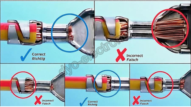
It makes a cold, gas-tight metal joint. Applicator dies squeeze the terminal barrel past its elastic limit, so the barrel and the stranded conductor deform together into one mass. Air and moisture get pushed out of the interface. With no oxygen inside, the copper does not tarnish, and contact resistance stays low for years. No heat, no flux, no molten filler. That is the whole mechanism.
A terminal has two crimp zones, and they do different jobs. One zone, the conductor crimp, grips the bare strands and carries the current. Another, the insulation crimp, grips the jacket and takes the mechanical load, so bending and tugging never pull directly on the electrical contact. Both zones have their own geometry. Get either one wrong and the joint fails a different test. IPC/WHMA-A-620 is the industry’s consensus benchmark for cable and wire harness assemblies, and it defines acceptance classes for exactly this kind of workmanship.
Check the die first. That single habit prevents more bad crimps than any downstream inspection.
Why Production Lines Skip Soldering
Because soldering puts too many variables into one joint. Heat, solder volume, flux residue, dwell time, and operator technique all move the result. Flux left behind corrodes from the inside. Heat softens or shrinks the insulation near the barrel. Molten solder wicks up between the strands and turns flexible wire into a rigid rod, so vibration concentrates the bending stress at the point where the wicking stops. None of that shows up on a prototype. It shows up after thermal cycling and shake.
A crimp collapses those variables into a die set and a press. Once the crimp height and the applicator are validated, part one and part ten thousand come off the same tooling with the same force. Consistency belongs to the equipment, not to whoever is on shift. That is why automotive and aerospace harness programs default to crimping, and why our wire harness vs cable assembly breakdown treats termination method as a build decision rather than a preference.
Here’s the thing: solder dies at the wicking line. A joint can look fine under a bench microscope and still fail where the stiff section ends. Gas-tight crimps don’t have that transition, so strands keep moving with the harness.
To be fair, crimp is not universal. Very fine wire, an unusual terminal, a field repair, or a handful of prototype boards can still be faster to solder. And IPC/WHMA-A-620 does not declare one method superior. DYC’s comparison of crimp and solder notes that the standard accepts both under different acceptance criteria, with pull-force verification for crimps and visual workmanship criteria for soldered terminations. For volume production where reliability matters, though, the tool-controlled process wins.
Wire Harness Crimping Quality: Five Checks
Five measurements decide pass or fail, and none of them is a guess. Crimp height is the critical one. Too high leaves the strands loose, so resistance climbs and pull force drops. Too low crushes the strands, and a cross-section shows flattened or broken wires with a smaller effective conductor area. Crimp width and barrel shape come from the die: look for symmetrical deformation, no burrs, and no twisted terminal.
Conductor and insulation position matter just as much. Every strand must sit inside the conductor zone, with no stray strands outside. Jacket ends must sit under the insulation grip, yet never enter the conductor zone, because a film of plastic in the contact interface gives you an intermittent open. Pull force is the direct mechanical verdict, the force needed to separate wire from terminal. Finally, a crimp cross-section, cut and polished, reveals voids, incomplete strand deformation, and barrel cracks. It is the reference method when a setup is disputed.
Where Do Wire Harness Crimping Limits Come From?
Numbers come from documents, not memory. Crimp height targets and minimum pull force are set by the terminal and wire datasheets, by the pull-force table in IPC/WHMA-A-620, or by USCAR-21 on automotive programs. As one data point you can quote: IPC/WHMA-A-620 Table 19-8 defines minimum pull-force values by wire gauge, and the representative minimum for 30 AWG copper is 6.7 N (1.5 lbf) in the widely cited crimping standards table. Confirm the exact figure against the governing standard revision and your terminal datasheet before you release a setup. USCAR-21 adds a crimp height process tolerance of about ±0.05 mm and mandatory cross-section validation, per this standards comparison. Different terminal, different wire, different number. Every time.
We log those five checks on the incoming quality control record and repeat them at first article inspection. Same form, same limits, no exceptions for a rushed lot.
Which Wire Materials Break One Set of Crimp Parameters?
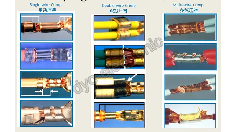
Almost all of them. Wire choice is the variable people underestimate. Copper conductor sizes run from 30 AWG up to 4/0 AWG, and covering that span takes automated crimping stations plus manual workstations for special sizes and low-volume prototypes. Across that range, terminal part numbers, dies, crimp heights, and pull-force limits are several different setups, not one.
Insulation changes the insulation grip as well. PVC, XLPE, PUR, silicone, and PTFE differ in hardness, spring-back, and temperature rating, so how tightly the grip closes and whether it damages the jacket have to be re-tuned per material. Assemblies are built for a −40 °C to +150 °C operating window, with foil, braid, or combination shielding options. Each choice alters outside diameter and construction. Here is a representative material view:
| Material | Typical application | Temperature range | Key benefit |
| Cross-linked polyethylene (XLPE) | High-temperature engines | −55 °C to 150 °C | Superior thermal stability |
| Teflon® (PTFE) insulation | High-temperature industrial | −70 °C to 260 °C | Chemical resistance |
| Aluminum conductors | Weight reduction | −40 °C to 125 °C | 40% weight savings |
| PVC insulation | General automotive | −40 °C to 105 °C | Cost-effective protection |
Those figures came from a customer-supplied selection table. They’re material ratings, not assembly ratings, so check each one against the wire maker’s datasheet before you sign off a setup.
Wire Harness Crimping Temperature Ratings: Two Different Numbers
Two different numbers are in play here, and mixing them causes real trouble. Rows in that table give each material’s rated temperature range. Assembly operating range is −40 °C to +150 °C. An assembly is only as capable as its weakest link across insulation, terminal, shield, jacket, and connector housing, so you cannot take the highest value in the table and apply it to the finished harness. Not even close.
One more row deserves attention. Aluminum conductors cut weight by 40%, which is attractive, but aluminum oxidizes at the surface and creeps under sustained pressure. Terminal plating, contact preparation, crimp height, and pull-force limits all need their own qualification. Change the conductor metal and you repeat the five checks from scratch. That is the plainest reason one parameter set cannot cover a whole product family. Our box build work runs into the same issue one level up, where harness, board, and enclosure tolerances have to agree.
Crimp Defects, and the Adjustment That Fixes Each
Most crimp defects trace back to one of three setup errors. Height too high means loose strands, rising contact resistance, and easy pull-out; drop the applicator shut height and re-run pull force plus a cross-section. Height too low means damaged or broken strands and a reduced conductor section; raise it, or move to the correct die size for that terminal. Insulation pushed into the conductor zone leaves plastic in the contact path and produces an intermittent connection, so fix strip length and wire positioning first.
Stray or exposed strands oxidize, risk shorting to neighbours, and scatter the pull-force readings; check whether stripping nicked the conductor and whether the terminal matches the wire gauge. A skewed terminal with burrs will not seat in the housing and can score the jacket, so inspect die wear and terminal feed alignment. Each fix looks like a press adjustment. It is really a cleanup step for everything downstream.
Crimping is not the end of the line. Soldering, overmolding, potting, labelling, and full connector integration all follow, and every one of them inherits the state the crimp left behind. A terminal that sits a fraction off-axis, or a crimp with a slightly larger outside diameter, turns into a housing that will not latch or an overmold that flashes. Downstream integration amplifies small crimp errors. Cheap to fix at the press, expensive to find at final assembly.
How Is Wire Harness Crimping Verified Before Shipment?
In three layers, with the last one at 100%. First article confirmation covers dimensions, pull force, and cross-section. In-process patrol checks crimp height at intervals and counts die cycles. At the end of the line, every assembly goes through 100% continuity testing and mechanical pull-force testing, because the two catch different defects: continuity catches a wrong netlist connection, while pull force catches a weak mechanical bond. Skip either and something gets through. Cloom’s harness manufacturing process guide lists 100% electrical continuity testing as a standard process benchmark, which matches how we gate a lot.
Holding a 100% gate steady takes more than a test bench. DYC electronic runs a controlled OEM cable assembly facility with a certified quality system and repeatable production processes, configured for precision OEM cable and wire harness production with full quality control across the whole process. Crimp parameters, die numbers, wire lots, and test results stay on file, so a field question can be traced back to a specific shift, die, and reel of wire. Automotive IATF 16949, aerospace AS9100, and industrial ISO 9001 programs ask for precisely this layer, and the IPC-A-610 Class 3 discussion on our site covers the same acceptance mindset on the board side. One controlled flow runs from prototype units through to large-scale OEM production, so a parameter tuned during the sample stage does not quietly drift once volumes rise.
Dies wear. Terminal lots change. So “we set it up last time” proves nothing. Re-run the first article after a material change, a die change, or a shift change. It is far cheaper than sorting a finished batch.
Four Questions Engineers Ask About Wire Harness Crimping
What Is the Right Wire Harness Crimping Height?
There is no universal value. Take it from the terminal and wire datasheets, the IPC/WHMA-A-620 pull-force table, or USCAR-21 for automotive work. Change the terminal and you re-qualify the height. A number copied from a different part number is the most common setup mistake we see.
How Much Pull Force Should a Crimp Hold?
Follow the standard table and the datasheet, and expect the requirement to rise with wire gauge. Memorizing one figure is not the point. It is testing every lot against one agreed limit and keeping the record. On a production line this test is run on every assembly, not released by sampling.
Which Is Better for a Harness: Crimping or Soldering?
It depends on the application. For volume, vibration, and repeatability, crimp. For very low quantities, field repair, odd terminals, or a geometry that only accepts solder, soldering still has a place. Neither method replaces the other everywhere.
Can Wire Harness Crimping Be Reworked?
Basically no. Crimping is permanent plastic deformation. A bad terminal gets cut off and replaced, not pressed a second time. That irreversibility is exactly why first article approval matters more than any repair step.
Why Wire Harness Crimping Cannot Run on Feel Alone
It looks like the least interesting step on the line, one second per termination. Yet it decides electrical contact, mechanical strength, and long-term oxidation behaviour at once, and none of those three can be confirmed by looking at the finished harness. Wire harness crimping has to be treated as a controlled process, not a craft.
When we trace an intermittent open or contact resistance that climbed over time, the root cause is often a strip length that drifted on one reel, or a die that went past its service life. Assuming the setup holds forever is the most expensive misjudgement in harness work. Ask which die made the parts, and how the first article was recorded.
If your drawing calls out a crimp height tolerance and a pull-force table, ask your supplier those two questions before releasing the build. That’s it. No magic spec, no clever fixture. Just a die number and a record somebody can actually find six months later.
 Français
 English
 Русский
 Deutsch
 日本語
 한국어
 Español
 Português
 العربية
 Türkçe
 Italiano
 Polski
 Dansk