
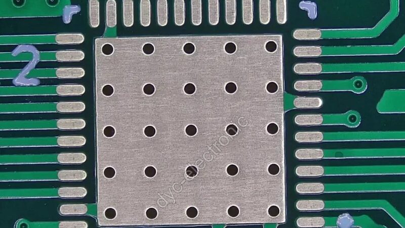
A couple days ago something happened on the line, and it really stung. A batch of 0.4mm QFP boards looked fine to the naked eye right off the printer, but two hours later every single one failed functional test. We cracked open the parts and looked — man, the leads just never got any solder on them. Under the microscope it was obvious: the root was the very first process — the paste on the pad was already 20% short, and before reflow there just wasn’t enough material, so no way it was going to solder right after that.
That’s why now I’ll go to bat with the boss to get 3D SPI on the line. Solder paste inspection (SPI) has to sit right behind the printer and in front of the reflow oven, catching the problem in the crib. Find it after the board’s already done? Too late! On every one of our fine-pitch lines, on every first-article, this step has to run — no discussion.
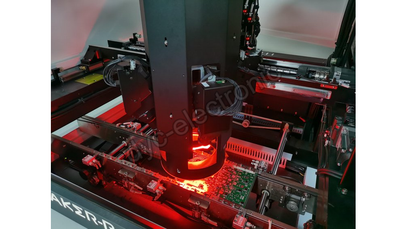
Skip SPI? That’s Tuition We Can’t Afford
Anyone in SMT knows there’s a number in the industry: 60% to 70% of defects are caused by the printing step. In a mixed-line shop like ours, that number isn’t exaggerated one bit. The printer is the earliest place on the whole line to go wrong, and also the cheapest place to go wrong. If you don’t hold the line here, later you either brute-force catch it with AOI, or it just flows straight to the customer and you take the beating.
There’s a cost math here that ASC International worked out, and I think it’s spot on: catch one bad print at SPI, fix it for fifty cents; wait till AOI catches it, and it’s fifty bucks to start; get to the customer site and one board won’t even stop at five hundred. The further you drag it out, the more the cost climbs exponentially.
We’ve had a hard-learned lesson before. A batch of 0.4mm QFP, because someone didn’t trust this SPI gate, and the whole reel got scrapped. That pad is only 0.18×1.0mm, the volume about 300nL, lose 20% and the lead just won’t climb up. Later we checked SMTmachine’s data and it matched exactly what we saw under the scope. So I’m telling you, this gate — you’ve got to trust it.
2D or 3D? Don’t Overthink It, Just Go 3D
If anyone still asks me 2D or 3D, I’ve got one line: go 3D, don’t hesitate.
A 2D system can only see a shape, the height is all “guessed.” And that guess can be off from the real 3D reading by 10% to 15%, with a false-call rate as high as 3% to 5%. On a fine-pitch QFP, you can’t even tell whether the lead will climb up after reflow — what’s the point of it?
3D SPI measures height, volume, and area directly. A good machine gets volume accuracy to ±2%, height ±1µm, false calls under 1%. On our fine-pitch lines we run a 3D SPI using phase-measuring moiré (PMP) — why? Because it reads down to sub-micron, and it isn’t picky about the board color, dark solder mask or bare copper, it’s not afraid of either. Laser triangulation is fast but it’s scared of vibration, doesn’t fit a high-precision setup like ours.
Don’t Just Look at the Picture, Watch These Tolerance Numbers
No matter how pretty the 3D picture is, it’s hollow — what really gates the board is the tolerance. These numbers are the process window SMTmachine gives, and they’re our baseline for tuning the machine:
Volume ±15%25%: catches low or stacked paste Height ±1020µm: catches low paste or bridging risk Area ±10%15%: catches stencil aperture transfer error Offset ±2550µm: catches stencil alignment drift
Listen, these ranges are tuned per package, not one value for the whole line! Set them too tight and the screen floods with false calls, drives the operators crazy; set them too loose and real defects slip through. There’s also one that’s easy to miss: coplanarity. The leads have to be within ±25µm or the paste won’t sit flat. That one’s supposed to be checked at placement, but it explains half the complaints of “paste’s fine but the joint still fails.”
Where Does SPI Go? Right Behind the Printer, Don’t Move It
SPI’s spot isn’t up for debate — right behind the printer, in front of the placement machine. Its whole point is to catch the bad one before the board even eats a component.
Our line is in-line — the board slides from the printer to SPI to the placement machine, never touching the floor in between. SPI alarms, line stops, printer wipes the stencil. This loop is way faster than finding the trend three stations later. Some shops still do batch offline inspection, and on fine-pitch that’s just begging for pain — by the time you’ve read the trend, a whole line’s worth is already wrecked. Miss one trend and it’s not one scrap board, it’s a whole batch!
The Stencil Is the Daddy, SPI Is Just the Witness
Speaking from the bottom of my heart: the stencil is more fundamental than SPI. SPI only tells you “the paste’s wrong,” not “why it’s wrong.” Aperture worn, stencil dirty — SPI can scream all day and it won’t help.
So on fine pitch we wipe the back of the stencil every 3 to 5 boards; printing speed held at 2550mm/s, paste viscosity 180220Pa·s, separation 1~3mm/s. Get these process params right and they beat any software algorithm. I’d rather spend an hour tuning the stencil than a week tuning SPI alarms. Remember: SPI is a witness, not a doctor.
One more reminder: SPI can’t catch a flipped component or a wrong-value part. It only sees paste. Pair IPC-A-610 Class 3 at AOI for acceptance, and most of the holes get plugged before shipment.
Pits We’ve Stepped In — Don’t Step in Them Again
Tolerance copy-paste: can 0201 and a connector use one window? Tune per package — that’s common sense. No alignment datum: SPI and the printer not using the same fiducials, every reading drifts. Slow reaction: SPI alarms, operator clicks “continue,” and the trend gets hidden. We pull the first three alarms each shift and review them; once we spotted a stencil going bad a week early. Used as pass/fail: SPI is actually a trend tool! Watch the volume creep down week by week and you’ll see the aging sign before the stencil fully dies. Titoma explains this usage for mixed-line shops really well — worth a look.
A Few Frequently Asked Questions
Does every board need inspection? Fine pitch or high volume, must inspect. 0.5mm BGA, 0.4mm QFP — the margin is nearly zero, 100% SPI pays back fast. A board that’s all coarse-pitch big resistors, first-article sampling is fine. But anything with a sub-0.5mm BGA, recommend full inspection — the fault tolerance is just too small.
3D costs more than 2D, is it worth it? Usually yes. ASC’s ROI model figured a $200 board saves about $750k a year, paying back in around four months. Of course it depends on your volume, but on fine-pitch lines, 2D’s estimation error really can’t be borne.
Can SPI replace AOI or X-ray? No. SPI only sees pre-reflow paste; AOI catches missing and wrong parts; X-ray sees the hidden joints under BGAs. A proper line needs all three, each doing its own job.
How often do you clean the stencil so SPI stops screaming? Fine pitch, clean the back every 3~5 boards; coarse pitch, every 10. A dirty stencil prints less and SPI’s defect rate spikes instantly, even if the machine itself is fine.
A Few Last Words
Fine-pitch lines, every first article — SPI in-line, go 3D. The printing step eats more than half of SMT defects; it’s the cheapest interception point. Get the stencil tuned first, then set tolerances per package, and treat SPI as a trend, not just a gate — it can lay the paste-decline trend right in front of you weeks before a mass scrap.
 Español
 English
 Русский
 Français
 Deutsch
 日本語
 한국어
 Português
 العربية
 Türkçe
 Italiano
 Polski
 Dansk