
Choosing the right wire harness vs cable assembly starts before you request a quote. In casual conversation, engineers often swap these terms. On a purchase order, however, that ambiguity costs money. Mislabeling your interconnect can trigger a wrong quote or a product that fails in the field. Actually, these two constructs have genuinely different design requirements, manufacturing processes, and performance characteristics. This article defines each type clearly, explains the structural differences, and gives practical guidance on selecting the correct solution for your next build.
What Is a Cable Assembly?
A cable assembly is an organized grouping of one or more insulated conductors terminated at both ends with connectors or contacts. The defining characteristic is the common outer jacket running continuously from one terminated end to the other. This jacket provides environmental protection against moisture, abrasion, UV, and chemicals while bundling conductors into a manageable unit.
Furthermore, the outer jacket establishes a predictable impedance environment for electrical signals. Multi-conductor cables like shielded twisted pairs or flat ribbon cables are manufactured as continuous raw material. The manufacturer simply cuts to length, strips ends, and terminates with specified connectors. For projects requiring straightforward point-to-point connections, exploring custom cable assembly services can streamline procurement and ensure proper jacket material selection.
Common examples include USB and HDMI cables with molded boots, coaxial assemblies with SMA or BNC connectors, and multi-conductor shielded cables in medical equipment. Ethernet patch cables and IEC power cords also fall into this category. These assemblies typically suit point-to-point interconnections carrying a single signal type between two connectors.
What Is a Wire Harness?
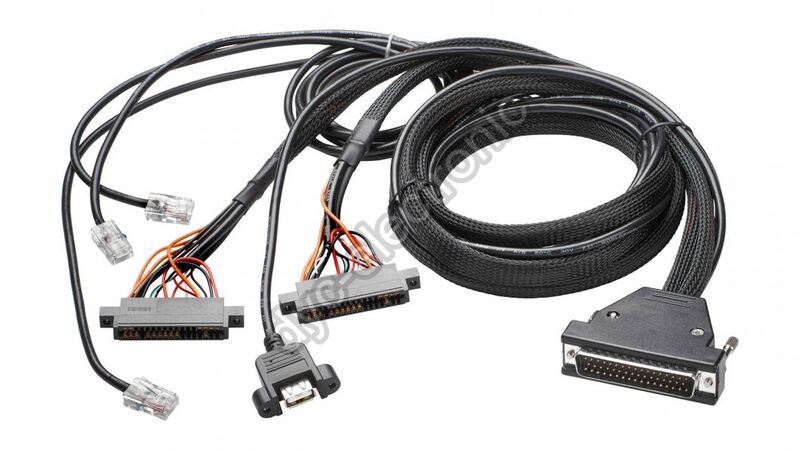
A wire harness (also called a wiring harness or cable harness) is an organized assembly of multiple individual wires routed together along a defined path. Unlike cable assemblies, these wires lack a common factory-extruded jacket. Instead, they are bound into a single unit using protective coverings applied during assembly—typically woven sleeves, braided shielding, corrugated conduit, PVC tape, or lacing cord.
Critically, the harness branches at defined points. Individual wires or sub-groups route to different connectors or termination points, forming a tree-like structure rather than a linear path. A harness does not go from connector A to connector B; it goes from a main trunk to connectors A, B, C, D, and E, with specific wires breaking out at precise branch locations.
Where Wire Harnesses Are Used
Automotive engine wiring harnesses connect ECUs to sensors, injectors, and ignition coils throughout the engine bay. Aircraft avionics harnesses route signals from avionics bays to cockpit instrumentation across the airframe. Industrial machine harnesses link control panels to motors, limit switches, and HMI devices. Medical device internal harnesses connect main PCBs to displays, sensors, and external connector panels.
In practice, if your product integrates multiple subsystems within a complex enclosure, you likely need a harness. For integrated builds combining harnesses with board-level assembly, reviewing PCBA manufacturing capabilities ensures seamless system integration.
Structural Differences: Wire Harness vs Cable Assembly
Understanding the physical distinctions prevents specification errors. Three areas matter most when comparing wire harness vs cable assembly: topology, protection, and production method.
Branching Topology in Wire Harness vs Cable Assembly
A cable assembly has a linear topology with a defined start and end. A harness has a branching topology where sub-trunks emerge from a main trunk at specified breakout points. This branching is defined by a harness drawing specifying every branch length, breakout location, wire gauge, color code, and terminal type.
Protective Covering Methods
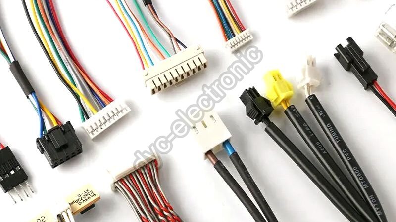
Cable assemblies rely on the cable’s own extruded jacket as the primary protective element. Wire harnesses require protective covering applied during assembly since individual wires have no common jacket. The choice—expandable braid, corrugated split loom, PVC tape wrap, or heat-shrink tubing at branch points—depends on vibration, temperature, fluid exposure, and abrasion resistance requirements.
Manufacturing Process Differences
Cable assemblies can be manufactured largely with automated equipment including wire cutters, strippers, crimping machines, and connector insertion tools. Wire harnesses demand significantly more manual labor, particularly at branch points and routing steps. Technicians must position individual wires on a formboard—a physical template holding the harness in its correct routed geometry while it is taped or sleeved.
Engineer’s Note: Incomplete harness documentation is the primary cause of errors and rework. Invest time upfront to make your drawing package complete. A missing branch length or unclear breakout location will stall production and inflate costs.
When to Use Each: Wire Harness vs Cable Assembly Decision Guide
Selecting the right wire harness vs cable assembly depends on five practical factors. Here is how we approach this decision on the line.
Choose a Cable Assembly When
- You have a point-to-point connection carrying one signal type (power, data, RF, video) between two connectors.
- The connection path is simple with no branching required.
- Environmental threats (moisture, abrasion) are addressed by selecting appropriate jacket material.
- Volume justifies automated termination processes.
- The cable must be field-replaceable and handled as a discrete unit.
Choose a Wire Harness When
- Multiple subsystems need electrical interconnection along a defined physical routing path.
- Wires must branch to three or more destinations from a common trunk.
- Space is constrained and individual wires must fit within a defined envelope.
- The product operates in harsh environments (automotive, aerospace, industrial) requiring organized, protected routing.
- Pre-built and tested subassemblies simplify final system assembly.
That said, some designs blur the line. If you have a mostly linear run with one small breakout near the end, discuss hybrid options with your CM rather than forcing a pure harness classification.
Design Considerations for Reliable Interconnects
For cable assemblies, key decisions involve conductor gauge (driven by current capacity and voltage drop), insulation material (temperature rating, chemical resistance, flexibility), shielding (for EMI-sensitive signals), and connector selection (mating cycles, current rating, environmental sealing). Specify these clearly in a cable assembly drawing with a wire schedule table.
For wire harnesses, a complete drawing package includes three elements: a wire schedule listing every wire’s gauge, color, start connector/pin, and end connector/pin; a schematic showing electrical connections; and a formboard or configuration drawing showing physical routing, all branch lengths, and covering specifications. Missing any of these invites costly back-and-forth during prototyping.
Testing Standards for Wire Harness vs Cable Assembly
Both cable assemblies and wire harnesses undergo continuity, short circuit, and Hi-Pot (high-potential dielectric) testing before shipment. Continuity testing verifies each expected electrical path connects the right source pin to the right destination pin. Short circuit testing confirms no unintended connections exist between isolated conductors.
Hi-Pot testing applies high voltage well above operating levels between conductors or between conductors and shield/ground to verify insulation integrity. This test is mandatory for safety-critical, high-voltage, or regulated applications.
For high-reliability sectors like aerospace, medical, and automotive, testing requirements follow IPC/WHMA-A-620—the cable and harness equivalent of IPC-A-610. Specifying the applicable standard and class in procurement documentation ensures your CM builds and inspects to a defined, verifiable bar. Refer to Molex cable assembly resources for additional application-specific testing guidance.
Frequently Asked Questions
What is the main difference between wire harness vs cable assembly?
The primary difference lies in topology and construction. A cable assembly uses a continuous factory-extruded jacket for point-to-point connections. A wire harness bundles individual wires with aftermarket protective covering and features branching routes to multiple destinations.
Can I use a cable assembly instead of a wire harness to save cost?
Sometimes, but only if your design truly requires point-to-point connectivity without branching. Forcing a cable assembly into a multi-destination routing application creates installation headaches and reliability risks. Conversely, specifying a full harness for a simple two-connector link wastes money on unnecessary manual labor.
How do I specify testing requirements for my wire harness vs cable assembly order?
Reference IPC/WHMA-A-620 and specify Class 2 (standard) or Class 3 (high-reliability) in your procurement documentation. Include continuity, short circuit, and Hi-Pot test parameters. Your CM should provide test reports matching your specified class before shipment.
Getting the wire harness vs cable assembly distinction right at the design stage prevents misquotes, rework, and field failures. Whether you need a simple point-to-point cable or a complex multi-branch harness, clear specifications and proper testing standards protect your project timeline and budget.
Ready to move forward? Send us your drawings for a free DFM review and competitive quote. Our team can validate your harness documentation completeness and recommend the optimal interconnect solution for your application.
 Français
  English
  Русский
  Deutsch
  日本語
日本語  한국어
한국어  Español
  Português
  العربية
  Türkçe
  Italiano
  Polski
  Dansk
Dansk