
Hardware engineers frequently encounter a critical pitfall in Type-C CC pin configuration: confusing legacy USB-A protocols with native Type-C behavior. Many designers mistakenly treat D+/D- as the core charging channel. Consequently, circuits may show correct 5V polarity yet fail to charge, trigger device recognition errors, operate only on one insertion side, or exhibit current limiting—especially with Apple devices. In nearly all cases, the root cause is incorrect CC1/CC2 termination. Therefore, this guide clarifies standard 5V Type-C CC pin configuration so you can implement reliable charging circuits immediately.
Core Principle: CC Pins Are the Sole Charging Channel
In any Type-C CC pin configuration, all charging identification, current negotiation, plug orientation detection, and USB Power Delivery (PD) fast charging rely exclusively on CC1 and CC2. Under standard C-to-C charging scenarios, D+ and D- do not participate in the handshake at all. This is a hard rule defined by the USB Type-C Specification. Specifically, CC pins serve as the dedicated Configuration Channel managing device role identification, orientation detection, 5V high-current negotiation, and PD high-voltage fast charging. Meanwhile, D+/D- pins retain only USB 2.0 data transmission functionality and provide backward compatibility with legacy USB-A charging protocols such as BC1.2 and Apple 2.4A.
Business Value Highlight: Correctly implementing the CC channel eliminates costly re-spins caused by charging incompatibility. For OEMs shipping consumer electronics, this directly reduces warranty claims and accelerates time-to-market.
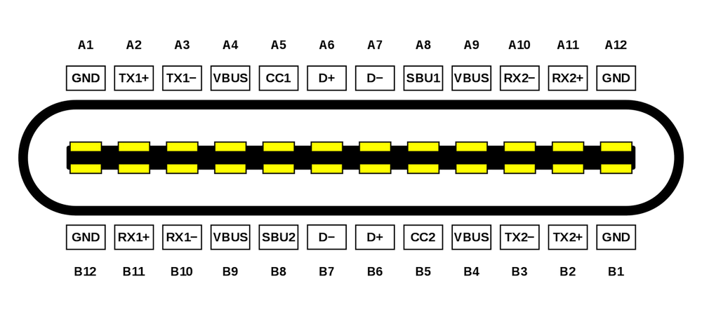
For detailed electrical specifications governing the Configuration Channel, refer to the USB Implementers Forum USB Type-C Specification.
Apple Type-C Charging Handshake Logic
Pure C-to-C Charging with Original Cable
In mainstream C-to-C scenarios, the entire handshake depends solely on CC1/CC2; D+/D- remain irrelevant. First, the charger applies a 56kΩ pull-up resistor on its CC line to broadcast its power source identity. Next, the phone applies a 5.1kΩ pull-down resistor on its CC line to identify itself as a sink. Subsequently, both devices negotiate through the CC pins to unlock 5V/3A or PD high-voltage profiles. Throughout this process, D+/D- may be left floating without affecting full-speed charging.
Legacy A-to-C Compatibility Note
However, the D+/D- dependent logic applies only when using older USB-A chargers. Native Apple Type-C ports do not rely on D+/D- for charging negotiation. Therefore, engineers designing USB-C charging circuit design must distinguish these two architectures clearly to avoid field failures.
Precise Functional Division: CC vs. D+/D-
CC1 / CC2: The Core of Type-C Intelligence
Every intelligent Type-C function is implemented through the CC pins with no alternative path. Primarily, pull-up resistors designate a Source (charger), while pull-down resistors designate a Sink (phone/device). Additionally, these pins enable orientation detection for blind-mate reversible plugging. Furthermore, they handle universal 5V high-current negotiation across all Type-C sink devices. Finally, the complete USB PD fast charging handshake for 9V/12V/20V profiles occurs entirely on this channel. Whether a Type-C device powers on, achieves fast charging, or draws rated current depends entirely on correct CC1 CC2 resistor network implementation.
D+ / D-: Compatibility Only, Not Primary Control
Conversely, D+/D- are fundamentally USB 2.0 differential data pairs. Within a Type-C receptacle, they serve exactly two purposes. First, they handle data transfer, firmware flashing, and serial communication. Second, they provide backward compatibility with legacy USB-A charger protocols including Android BC1.2 and Apple A-port 2.4A voltage-divider schemes. The distinction is absolute: new C-to-C architectures render D+/D- inactive for charging, whereas legacy A-to-C architectures activate D+/D- as a fallback for older fast-charging protocols. Understanding this division is essential for accurate Type-C sink source detection.
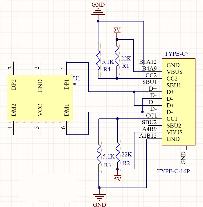
Four Standard CC Termination Schemes & Applications
Industry-standard resistor values are unified as follows: pull-up Rp = 56kΩ / 22kΩ / 10kΩ (to VBUS); pull-down Rd = 5.1kΩ (to GND). These values are defined in the USB Type-C Specification Table 4-26, and adherence ensures interoperability across certified cables and adapters.
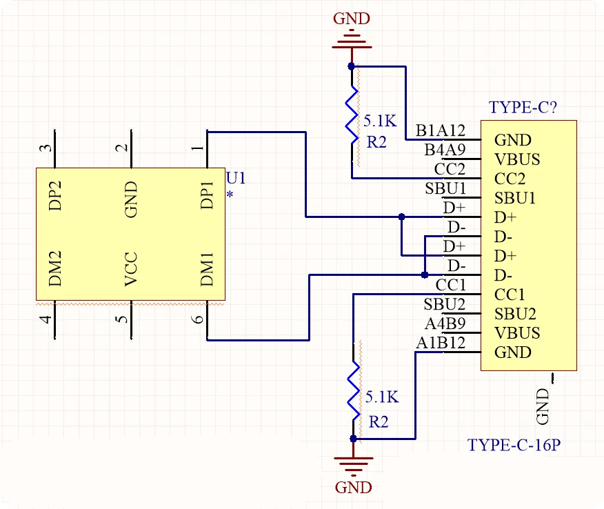
Scheme 1: Dual 5.1kΩ Pull-Down on CC1/CC2 (Sink Device)
This scheme applies to smartphones, development boards, MCUs, and small appliance control boards requiring a charging Type-C port. Functionally, chargers identify the device as a load, supporting reversible plugging and normal 5V/PD charging.
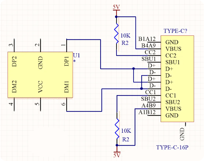
Scheme 2: Dual Pull-Up Resistors on CC1/CC2 (Source Device)
Typically, this configuration suits compliant Type-C chargers and power bank C-port outputs. It broadcasts power source identity, allowing Apple and Android C-port devices to perform CC handshake upon insertion. Moreover, different resistor values unlock different current capabilities. As a compatibility note, supporting legacy A-to-C fast charging requires adding a separate D+/D- divider or dedicated identification IC. Importantly, this addition does not interfere with native C-port fast charging.
Scheme 3: Coexisting Pull-Up and Pull-Down (Dual-Role Port)
Docking stations, portable power stations, and bidirectional Type-C devices use this approach. Consequently, the port automatically switches between Source and Sink roles, ensuring compatibility with all cable types and connected devices.
Critical Warning: Never Short CC1 and CC2 to a Single Pull-Up Resistor
Shorting CC1 and CC2 together and connecting them to one pull-up resistor causes poor compatibility. Specifically, Apple devices may fail to charge correctly, and E-Marker cables will not be recognized. Therefore, each CC pin must have its own independent termination resistor in any valid Type-C CC pin configuration.
Business Value Highlight: Proper dual-role port design enables a single SKU to serve both charging and powered-device markets, reducing BOM complexity and inventory costs for contract manufacturers.
If your project requires validated Prototype PCB Assembly services with tested Type-C implementations, our engineering team can verify CC termination compliance before mass production.
Frequently Asked Questions
Q1: Why does my Type-C device show 5V but refuse to charge even though polarity is correct?
The most common cause in Type-C CC pin configuration is missing or incorrect CC1/CC2 termination. Without a proper 5.1kΩ pull-down on the sink side, the source never detects a connected device and will not enable VBUS output beyond safe defaults. Therefore, verify both CC pins have independent 5.1kΩ resistors to GND per the USB Type-C Specification.
Q2: Do D+/D- pins affect C-to-C charging speed with modern phones?
No. In pure C-to-C USB-C charging circuit design, D+/D- play zero role in charging negotiation. Instead, all current and voltage agreements occur exclusively through CC1/CC2. D+/D- only become relevant when a legacy USB-A adapter is used with an A-to-C cable, triggering BC1.2 or Apple 2.4A fallback protocols.
Q3: Can I short CC1 and CC2 to save component count in my Type-C design?
Absolutely not. Shorting CC1 and CC2 to a single pull-up resistor breaks Type-C sink source detection, causes Apple device charging failures, and prevents E-Marker cable recognition. Thus, each CC pin requires its own independent resistor. The marginal cost saving is far outweighed by field failure risk and certification non-compliance.
 Français
  English
  Русский
  Deutsch
  日本語
日本語  한국어
한국어  Español
  Português
  العربية
  Türkçe
  Italiano
  Polski
  Dansk
Dansk